Choosing Big Drill Bits is not simply a matter of selecting the largest diameter. The correct choice depends on rock strength, formation abrasiveness, drilling depth, machine torque, and flushing capacity. A bit that looks powerful on a supplier’s page may overheat, vibrate, or wear quickly underground.
Industry data supports careful evaluation. The U.S. Geological Survey’s Mineral Commodity Summaries tracks mineral production, reserves, and extraction pressures worldwide. These trends matter because harder formations and deeper deposits demand more durable drilling systems. The International Association of Drilling Contractors also publishes safety and performance data, reminding buyers that penetration speed cannot be separated from operator control, equipment condition, and maintenance. Deloitte’s Tracking the Trends reports similarly identify productivity, automation, and equipment efficiency as major mining priorities.
As drilling-engineering authority J.J. Azar stated, “The drill bit is the business end of the drilling system.” That practical view should guide every purchase. Look closely at carbide button shape, tooth spacing, steel quality, connection type, and recommended operating speed. Imagine the bit cutting through fractured granite while water carries dust from the hole. Small design details can determine whether the job stays smooth or becomes expensive.
Still, no checklist is perfect. Rock conditions can change within a few meters. Supplier claims may also require verification through test records, warranty terms, and references from comparable sites. The following tips explain how to compare Big Drill Bits using measurable specifications, field experience, and realistic operating conditions. Performance matters. So does evidence.
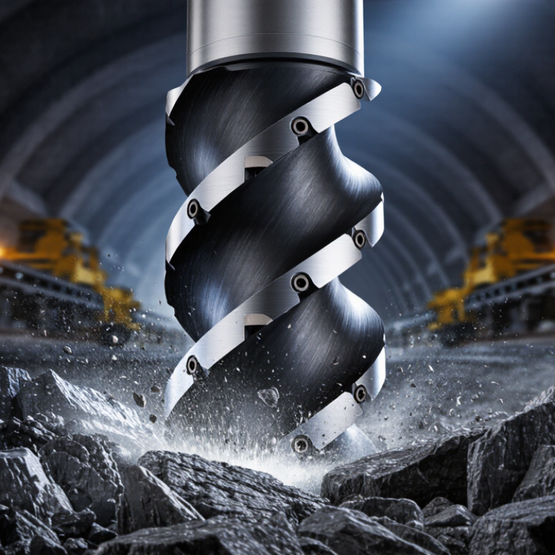
Define Drill Size and Point Geometry: 118° Versus 135° Cutting Angles
Choosing a big drill bit starts with defining the required hole size. Measure the cutting diameter, not the shank diameter. A small error can affect fastener fit, clearance, and material strength. Large bits also create more torque, so the drill must handle the load safely.
A 118° point is common for general-purpose drilling. Its sharper angle cuts quickly in wood, mild steel, and other softer materials. However, it may wander when starting on a smooth surface. Use a center mark or pilot hole when accuracy matters. The cutting edges should meet evenly at the tip.
A 135° split point behaves differently. Its flatter geometry reduces walking and usually needs less downward pressure. This makes it useful for stainless steel, harder steel, and other demanding materials. It can start more accurately, but it may feel slower in soft materials. Keep the drill rigid, reduce speed as diameter increases, and use suitable cutting fluid when heat builds.
I once selected a bit by diameter alone. That was a mistake. The point geometry mattered more than expected. A large 118° bit cut aggressively but grabbed near breakthrough. A 135° bit produced a cleaner start, yet required better alignment. Check runout, chuck capacity, flute condition, and the material before buying. Even a premium-looking bit can disappoint if its angle does not match the job.
Check Shank Diameter, Chuck Capacity, Length, and Runout Limits
When buying large drill bits, start with the shank diameter.
It must fit the machine’s chuck capacity, not just the bit’s cutting size. A 32 mm bit with a 13 mm shank may fit one drill, while a full-size shank may not. Check the chuck jaws, arbor, and locking method before ordering. Measure twice.
Length also affects control.
A longer bit can reach deeper holes, but it flexes more under pressure. That flex may enlarge the hole or leave a rough wall. For a short steel plate, choose the shortest working length available. For deep drilling, confirm the flute length and clearance space. I once selected a bit by total length alone. That assumption was wrong.
Runout deserves careful attention.
Mount the bit cleanly, then check the shank with a dial indicator. A small error at the shank becomes larger at the cutting tip. Excessive runout can cause vibration, uneven wear, and oversize holes. Compare the measured result with the tool maker’s stated limit. If no limit is provided, ask for a documented tolerance. Do not judge accuracy by eye. It feels precise. It is not. Also inspect the chuck for dirt, worn jaws, or damage, because the bit may not be the real source of movement.
Set RPM and Feed with the Formula RPM = 3.82 × SFM ÷ Diameter
Choosing a large drill bit starts with speed, not guesswork. Use RPM = 3.82 × SFM ÷ Diameter, with diameter measured in inches. SFM means surface feet per minute. For a 2-inch bit at 60 SFM, the calculation gives about 115 RPM. Check the material, bit geometry, and supplier’s cutting range before drilling. The formula sets speed, not feed. Feed rate still depends on chip load, flute count, and machine rigidity.
Keep the workpiece clamped firmly. Large bits can grab suddenly. Use a pilot hole only when the tooling guidance allows it; an oversized pilot may reduce cutting stability. Apply suitable coolant, clear chips frequently, and reduce feed near breakthrough. Listen for squealing, watch for blue chips, and stop if the spindle stalls. OSHA reports that machine-related incidents cause roughly 18,000 amputations and 800,000 injuries annually in the United States. Safe setup is not optional.
A practical check is simple. Measure the actual diameter. Confirm the SFM range. Calculate RPM. Set a conservative feed. Watch chip shape. Recheck vibration after every adjustment. I sometimes begin below the calculated speed, especially with a flexible setup. That choice may reduce productivity, but it exposes mistakes earlier. The 2024 Machine Tool Annual Report from the Association for Manufacturing Technology shows how strongly production depends on machine capability and process control, not cutting speed alone. Big bits punish careless assumptions. And formulas need judgment.
10 Tips for Buying the Best Big Drill Bits — Set RPM and Feed with the Formula RPM = 3.82 × SFM ÷ Diameter
| Tip |
Selection or Operating Factor |
Recommended Practice |
Material Example |
Drill Diameter
(in) |
Starting SFM |
Calculated RPM |
Feed per Revolution
(in/rev) |
Feed Rate
(in/min) |
| 1 |
Choose the correct drill material |
Use a general-purpose high-speed steel drill for moderate production and varied shop work. |
Mild steel |
0.500 |
80 |
611 |
0.008 |
4.9 |
| 2 |
Match the point geometry to the workpiece |
Use a split-point geometry to reduce walking and improve starting accuracy on large holes. |
Low-carbon steel |
0.750 |
60 |
306 |
0.008 |
2.4 |
| 3 |
Reduce speed for work-hardening alloys |
Use a lower cutting speed, firm feed, and continuous cutting action to help prevent work hardening. |
Austenitic stainless steel |
1.000 |
40 |
153 |
0.006 |
0.9 |
| 4 |
Allow for the larger diameter |
As drill diameter increases, reduce RPM to maintain the selected surface speed at the cutting edge. |
Cast iron |
1.250 |
60 |
183 |
0.008 |
1.5 |
| 5 |
Use a higher speed only with suitable materials and cooling |
Aluminum permits a higher starting SFM, but use cutting fluid or suitable coolant to control heat and chip welding. |
Aluminum alloy |
1.500 |
250 |
637 |
0.012 |
7.6 |
| 6 |
Control chip formation in brass |
Use a sharp drill and a controlled feed; a slightly reduced rake may help limit grabbing in some brass alloys. |
Brass |
0.750 |
150 |
764 |
0.010 |
7.6 |
| 7 |
Use rigid workholding |
Clamp the work securely and support thin sections or plates to reduce vibration, deflection, and burrs. |
Medium-carbon steel |
1.000 |
60 |
229 |
0.008 |
1.8 |
| 8 |
Use pecking when chip evacuation is difficult |
For deep holes, use controlled pecks and withdraw the drill to clear chips; avoid excessive pecking that can rub the hole. |
Stainless steel |
1.500 |
40 |
102 |
0.006 |
0.6 |
| 9 |
Apply coolant consistently |
Use an appropriate cutting fluid where practical, especially for steel and stainless steel, to improve heat and chip control. |
Mild steel |
0.750 |
80 |
407 |
0.008 |
3.3 |
| 10 |
Verify machine capacity before buying |
Check spindle power, chuck or holder capacity, available stroke, rigidity, and the maximum permitted drill size. |
Aluminum alloy |
1.000 |
250 |
955 |
0.012 |
11.5 |
|
Calculation notes:
RPM = 3.82 × SFM ÷ drill diameter in inches.
Feed rate in/min = RPM × feed per revolution.
The SFM and feed values shown are practical starting points for general-purpose high-speed steel drilling. Actual settings should be adjusted for drill geometry, alloy hardness, hole depth, coolant, machine rigidity, and chip control. Reduce speed if overheating occurs, and do not exceed the drill or machine manufacturer's rated limits.
|
Verify ANSI B94.11M Compliance, Safety Features, Warranty, and Service Life
Buying large drill bits requires more than checking diameter and price. In my workshop, the first document I request is a dimensional and material specification sheet. It should clearly identify ANSI B94.11M compliance, applicable size ranges, and testing information. Do not accept a vague “industrial grade” claim without evidence. Compare shank design, cutting geometry, and recommended operating speed with your drill press. A bit that fits the chuck may still be unsuitable for the machine’s torque. Check for uneven coating, chipped edges, or a loose-looking shank before use. Small defects become obvious when the bit meets thick steel. I have sometimes focused too much on sharpness and ignored balance. That mistake creates vibration, heat, and rough holes.
Safety features deserve a practical inspection. Look for secure shanks, clear operating guidance, and geometry that helps control grabbing during breakthrough. Use eye protection, firm workholding, and cutting fluid suited to the material. Never treat a safety note as decoration. Ask how the seller verifies batch quality and whether technical advice is available. A written warranty should state coverage, exclusions, claim steps, and service contact details. Service life depends on load, speed, cooling, storage, and sharpening quality, not marketing language. Record hole count, material, and visible wear after each job. This simple log reveals whether performance is consistent. I would also test one bit before buying a full set. It costs time. It can prevent an expensive assumption.
Large Drill Bit Buying Guide: Common Diameter Equivalents
Compare common large twist-drill sizes in inches and millimeters, then verify ANSI B94.11M requirements, safety features, warranty coverage, and expected service life before purchasing.
The metric values are exact inch-to-millimeter conversions: 1 inch equals 25.4 millimeters. For large drill bits, confirm that the product documentation identifies the applicable ANSI B94.11M dimensional requirements, provides a secure shank and suitable cutting geometry, and includes clear operating instructions. A longer service life depends on correct speed, feed, lubrication, workpiece material, and proper storage; warranty terms should be checked separately because coverage varies by supplier and product.
Conclusion
Choosing the right Big Drill Bits requires more than selecting the largest available diameter. Start by defining the required hole size, material, and point geometry. A 118° point is suitable for many general-purpose applications, while a 135° split point can reduce walking and improve performance on harder materials. Compare HSS, M42 cobalt with 8% cobalt content, carbide, and coated options according to heat resistance, toughness, cutting speed, and expected service life.
Before purchasing, confirm the shank diameter matches your chuck capacity and check the tool’s overall length, working length, and allowable runout. Proper cutting conditions are equally important: calculate spindle speed with RPM = 3.82 × SFM ÷ Diameter, then select a suitable feed based on the material and drill size. Finally, verify ANSI B94.11M compliance, inspect safety features, and review warranty coverage and service support. These checks help ensure accurate holes, stable operation, longer tool life, and better value.

 SINOVO