10 Tips for Choosing the Right Well Drill Bit

Time:2026-09-07 Author:Mason
0%

Choosing the right Well Drill Bit is a technical decision with direct effects on penetration rate, footage, vibration, and total well cost. The U.S. Energy Information Administration’s Drilling Productivity Report shows that drilling performance varies sharply across basins, even when operators use similar rigs. Formation strength, depth, pressure, and directional demands change the bit’s working environment. A bit that performs smoothly in soft shale may fail quickly in abrasive sandstone. Small details matter. Cutter wear, nozzle condition, and torque response can reveal trouble before a costly trip.

Industry guidance supports a disciplined selection process. The International Association of Drilling Contractors (IADC) provides standardized dull-bit grading methods, helping engineers compare wear patterns across wells and vendors. Society of Petroleum Engineers papers also connect bit performance with weight on bit, rotary speed, hydraulics, and formation behavior. These are not isolated variables. A poorly matched bit can create excessive vibration, damaged cutters, unstable hole cleaning, or unnecessary replacement time. The U.S. Department of Energy’s geothermal drilling reports further highlight how temperature and hard-rock conditions reduce equipment life and complicate drilling decisions.

This guide presents ten practical tips for evaluating a Well Drill Bit before deployment. It considers PDC and roller-cone designs, rock strength, hydraulic efficiency, gauge protection, and operating limits. Field experience still matters. Laboratory data can look perfect, yet a bit may struggle after formations change within a few meters. That is an uncomfortable truth. Selection should therefore combine published test results, offset-well records, drilling-parameter trends, and post-run inspection. No single checklist replaces engineering judgment, but a careful checklist can expose weak assumptions early.
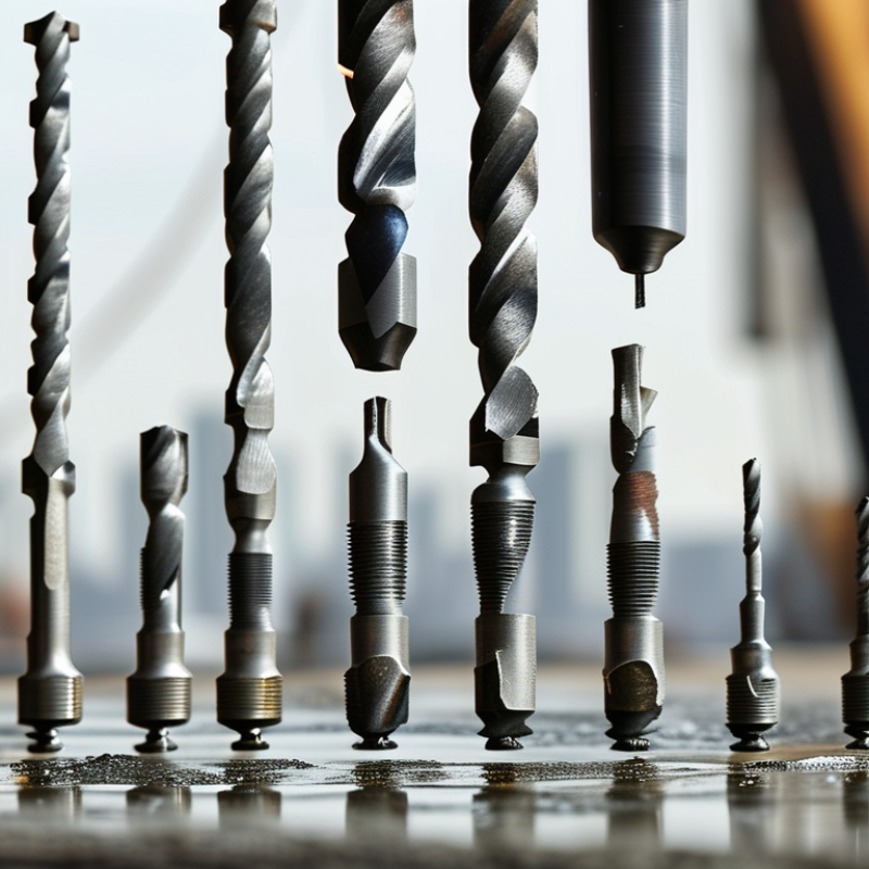
10 Tips for Choosing the Right Well Drill Bit

Define the Well Drilling Conditions and Project Requirements

10 Tips for Choosing the Right Well Drill Bit

Define the Well Drilling Conditions and Project Requirements

Start with the ground. Identify the formation before selecting a well drill bit. Soft clay, fractured limestone, dense granite, and loose gravel require different cutting structures. Review geological logs, core samples, and nearby drilling records when available. Small errors matter.

Record the planned depth, borehole diameter, inclination, and expected drilling speed. Water chemistry and temperature also affect bit performance. Abrasive formations can wear cutters quickly, while unstable layers may demand better hole-cleaning control. Measure twice. A bit suited to shallow water wells may perform poorly in a deep, high-pressure project.

Project limits are equally important. Check the available rig torque, rotation speed, pump capacity, and pullback force. The bit must match the equipment, not just the rock. Also define your tolerance for deviation, downtime, replacement cost, and sample quality. Experienced crews often balance penetration rate against service life. The fastest bit is not always the most economical choice.

Field conditions rarely match the original report perfectly. Geological predictions can be incomplete. That assumption deserves review. Plan a monitoring process for torque, vibration, penetration rate, and return flow during drilling. If these readings change suddenly, pause and reassess the formation or bit condition. A practical selection combines test data, operator experience, engineering calculations, and project-specific safety requirements.

Match Bit Design to Formation Type and Rock Hardness

Choosing the right well drill bit starts with the formation, not the rig schedule. Soft clay, fractured limestone, and hard quartz-rich rock require different cutting structures. The USGS describes calcite at Mohs hardness 3 and quartz at 7, showing why one bit design cannot perform equally across every interval. Softer formations often suit wider waterways and larger cutters. Hard, abrasive rock needs stronger cutter support and improved wear resistance.

Check the geological log before selecting the bit. Look for compressive strength, abrasiveness, porosity, fractures, and unexpected interbeds. SPE and IADC technical studies consistently link bit performance with formation strength, weight on bit, rotary speed, and hydraulic cleaning. In practice, excessive weight can damage cutters in soft rock. Too little weight may cause inefficient scraping in stronger layers. Watch torque, rate of penetration, vibration, and return-fluid condition during drilling. Small changes matter.

PDC designs can cut efficiently in relatively homogeneous formations, while roller-cone designs may tolerate broken or mixed rock more effectively. That distinction is useful, but not absolute. A field trial may contradict the geological model. I have seen a bit selected for “medium” rock struggle because thin abrasive streaks dominated the interval. Record dull characteristics after pulling out. IADC dull grading provides a consistent language for comparing cutter wear, tooth damage, and bearing condition across runs. Use those records to adjust cutter size, blade count, hydraulics, and operating parameters for the next section.

Compare Bit Types, Cutting Structures, and Drilling Methods

Choosing the right well drill bit starts with the formation, not the catalog. Soft clay, fractured limestone, and abrasive quartz demand different cutting structures. A fixed-cutter bit can deliver fast penetration in uniform rock. A roller-cone bit may handle broken, interbedded layers more patiently. Impregnated diamond bits suit extremely abrasive formations, although they often require higher operating cost.

Check rock hardness, abrasiveness, compressive strength, and expected temperature. Then match cutter density to the rock. More cutters can improve durability but may reduce cleaning efficiency. Review nozzle size, junk-slot area, and hydraulic pressure before ordering.

The U.S. Department of Energy’s GeoVision study estimates drilling and well construction can represent 30–50% of geothermal project costs. Small bit decisions can become expensive quickly. They deserve field data.

Match the bit to the drilling method. Rotary mud drilling needs reliable hydraulics and cuttings removal. Air rotary and down-the-hole hammer drilling require impact resistance and dust control. Reverse circulation can favor designs that protect sample quality. Set practical limits for weight on bit, rotation speed, torque, and flow rate.

Track penetration rate, footage, vibration, and energy use. Use the IADC dull-grade system, which records wear on a 0–8 scale, after each run. Compare cost per drilled meter, not purchase price alone. A cheaper bit can fail sooner. That lesson is easy to miss. Review the records with the driller, because laboratory predictions can overlook fractured ground, poor cleaning, or unstable operating habits.

Evaluate Bit Size, Durability, Compatibility, and Operating Costs

Choosing the right well drill bit starts with the borehole plan, not the catalog. Match the bit diameter to the casing program, formation, pump capacity, and required flow rate. A larger bit may improve clearance, but it can increase torque and fluid demand. The U.S. Department of Energy’s GeoVision analysis estimates drilling can represent 30–50% of geothermal project costs, so small sizing errors can become expensive.

Check durability through tooth design, cutter material, bearing protection, and junk-slot capacity. Hard, abrasive rock usually demands stronger wear resistance, while fractured formations may punish a very aggressive cutting structure. The IADC Drilling Manual recommends evaluating formation strength, abrasiveness, and hydraulic cleaning together. Do not judge durability by footage alone. Record penetration rate, vibration, damage, and bit condition after every run.

Compatibility is practical. Confirm the bit connection, rotary speed range, weight-on-bit limits, mud properties, and available horsepower. Compare expected footage with purchase price, trip time, repair cost, and lost circulation risk. A cheaper bit is not automatically economical. The U.S. DOE report also stresses that drilling performance depends heavily on local geology and operating conditions. My own caution is simple: cost models often look precise, but field data is incomplete. Leave room for uncertainty, and review the decision after the first few hundred meters.

Select, Test, and Maintain the Bit for Reliable Well Performance

10 Tips for Choosing the Right Well Drill Bit

Tip: Select the bit according to formation hardness, abrasiveness, and expected depth. A bit suited for soft clay may struggle in fractured limestone. Review drilling records, rock samples, and planned weight on bit before ordering. Tooth shape, cutter density, and hydraulic openings also affect performance. I have learned that a perfect choice on paper can fail when the formation changes unexpectedly.

Tip: Test the bit under controlled conditions before full deployment. Check penetration rate, torque, vibration, and return flow. Compare these readings with the drilling plan, not only with the previous bit. Watch for uneven wear on cutters or teeth. Small changes matter. If vibration rises, reduce operating pressure and inspect the assembly. Field judgment is valuable, but written measurements prevent memory from becoming misleading.

Tip: Maintain the bit throughout the run. Clean fluid pathways after use, remove packed formation, and inspect threads, cutters, bearings, and nozzles. Store the bit dry and protected from impact. Record footage drilled, operating hours, and visible damage. These records support safer selection later. Do not ignore minor wear. I once underestimated a small damaged cutter; the next run became slower and more expensive than expected. Good maintenance is practical, though it is not always perfect.

10 Tips for Choosing the Right Well Drill Bit - Select, Test, and Maintain the Bit for Reliable Well Performance

No. Selection or Maintenance Focus Recommended Practice Key Data to Review Why It Matters Field Check or Test Typical Action
1 Match the bit to the formation Use fixed-cutter bits for many homogeneous soft-to-hard formations and roller-cone bits where impact crushing and formation variability are important. Unconfined compressive strength, abrasiveness, interbedded layers, fractures, and expected compressive strength changes with depth. A bit designed for the formation can improve penetration consistency and reduce premature cutter or bearing damage. Compare offset-well lithology, drilling records, cuttings, and penetration-rate trends. Select the bit family and cutting structure that best fits the dominant formation.
2 Choose the correct cutting structure Balance cutter size, cutter density, tooth design, gauge protection, and backup cutting elements against the expected rock strength and abrasiveness. Cutter exposure, cutter count, tooth profile, gauge length, nozzle placement, and blade configuration. Larger or more exposed cutters can increase aggressiveness, while denser cutting structures generally provide more support in harder or abrasive rock. Check whether the design provides enough cutter support without restricting cleaning or hydraulic flow. Use a balanced design rather than selecting solely by nominal diameter.
3 Verify size and connection compatibility Confirm bit diameter, connection type, shoulder dimensions, torque requirements, and compatibility with the drill string, casing program, and hole section. Nominal bit size, connection specification, maximum operating torque, allowable rotary speed, and planned hole diameter. An incompatible connection or incorrect gauge can cause installation problems, poor hole quality, or costly nonproductive time. Conduct a dimensional inspection and verify connection details against the drilling program before running in hole. Reject any bit that does not meet the approved size and connection requirements.
4 Evaluate hydraulics and hole cleaning Select nozzle size, flow area, and hydraulic configuration to provide adequate bottom-hole cleaning without exceeding pump or pressure limits. Pump rate, standpipe pressure, nozzle total flow area, drilling-fluid properties, annular velocity, and solids loading. Insufficient cleaning can allow cuttings to accumulate, reduce penetration rate, and increase the risk of regrinding or balling. Confirm calculated pressure losses and monitor standpipe pressure, returns, and cuttings transport. Adjust nozzles or operating parameters within approved hydraulic limits.
5 Check operating limits Set a controlled operating window for weight on bit, rotary speed, torque, flow rate, and vibration based on bit design and downhole conditions. Recommended weight-on-bit range, revolutions per minute, torque response, differential pressure, vibration, and temperature exposure. Excessive load or speed can accelerate cutter wear, bearing damage, whirl, stick-slip, and other forms of mechanical failure. Start conservatively, then increase one parameter at a time while watching torque, vibration, and penetration response. Reduce load or speed when vibration, torque spikes, or penetration instability develops.
6 Inspect the bit before testing Perform a documented pre-run inspection of cutters, teeth, nozzles, threads, gauge pads, junk slots, seals, and visible welds or hardfacing. Cutter damage, loose components, blocked nozzles, thread condition, gauge wear, cracks, and manufacturing or handling damage. Finding defects before deployment prevents avoidable downhole failures and establishes a condition baseline for later comparison. Use visual inspection, dimensional checks, thread gauges where applicable, and photographs for the run record. Quarantine and investigate any bit with critical damage or uncertain condition.
7 Run a controlled performance test Use a gradual ramp-up of weight on bit, rotary speed, and flow while recording penetration rate and mechanical response. Rate of penetration, weight on bit, rotary speed, torque, standpipe pressure, vibration, pump rate, and drilling time. A controlled test shows whether the bit is cutting efficiently and identifies unstable operating conditions early. Compare trends at similar formation intervals and avoid judging performance from penetration rate alone. Keep the bit within the stable operating window that delivers consistent drilling progress.
8 Monitor wear and drilling efficiency Track performance continuously and record changes in penetration, torque, vibration, pressure, and cuttings character. Penetration-rate decline, torque fluctuations, rising pressure, vibration severity, cutter wear, and changes in cuttings size. Trend changes can indicate dulling, balling, nozzle plugging, formation changes, or inefficient hydraulics. Review time-based and depth-based trends rather than relying on a single sensor reading. Modify parameters or plan a trip when performance falls outside the defined criteria.
9 Apply correct handling and storage Protect cutters, threads, gauge surfaces, and nozzles during transport and store the bit in a clean, dry, supported position. Thread protectors, lifting equipment, storage environment, protective caps, impact exposure, and contamination. Improper handling can create damage that is mistaken for downhole wear and may compromise installation or performance. Inspect the bit after transport and before rig-up; verify that protective devices are correctly installed. Use approved lifting points and never drag or drop the bit.
10 Inspect, clean, and document after the run Clean the bit, remove packed formation material, inspect wear patterns, record dull condition, and compare results with the pre-run baseline. Cutter or tooth wear, broken elements, gauge loss, nozzle condition, bearing condition, junk-slot damage, and total drilled footage. Post-run analysis improves the next bit selection and helps distinguish normal wear from operating or formation-related damage. Photograph the bit, complete a standardized dull-grade report, and compare actual results with the drilling plan. Repair, refurbish, retire, or redeploy the bit according to inspection findings and approved procedures.
Core performance indicators: rate of penetration, drilled footage, cost per metre, torque stability, vibration level, hydraulic pressure, cuttings transport, and post-run dull condition.

FAQS

: How should I identify the ground before choosing a well drill bit?

: Review geological logs, core samples, and nearby drilling records. Soft clay, fractured limestone, granite, and gravel need different cutting structures. Small errors matter.

Which project details must be defined before selecting a bit?

Record depth, borehole diameter, inclination, drilling speed, water chemistry, and temperature. A shallow-water bit may fail in a deep, high-pressure hole. Measure twice.

How does the drilling rig affect bit selection?

Match the bit with rig torque, rotation speed, pump capacity, and pullback force. A suitable bit may still underperform with incompatible equipment.

How should bit diameter be selected?

Match diameter with casing plans, formation conditions, pump capacity, and required flow rate. A larger bit improves clearance but increases torque and fluid demand.

What features influence bit durability?

Examine tooth design, cutter material, bearing protection, and junk-slot capacity. Abrasive rock needs stronger wear resistance. Fractured ground may damage aggressive cutters.

How can I compare the true cost of different bits?

Compare purchase price, expected footage, trip time, repair costs, and lost-circulation risks. The cheapest bit may cost more later. Costs can surprise you.

What operating measurements should be monitored during drilling?

Track torque, vibration, penetration rate, and return flow throughout each run. Sudden changes may indicate formation shifts or bit damage. Pause and reassess.

Is the fastest-penetrating bit always the best choice?

No. Balance penetration rate, service life, hole quality, replacement time, and sample quality. The fastest option may increase downtime.

How should bit performance be reviewed after drilling begins?

Inspect the bit after each run and record footage, damage, vibration, and penetration rate. Review the choice after the first few hundred meters. Field predictions are imperfect.

Conclusion

Choosing the right Well Drill Bit begins with a clear understanding of the drilling environment and project goals. Consider the planned depth, hole diameter, drilling method, fluid conditions, expected pressure, and available equipment. The formation type and rock hardness are equally important, because soft soil, sand, clay, fractured rock, and hard formations each require different cutting structures and bit designs. Comparing options such as fixed-cutter and roller-cone styles can help identify the most suitable balance of penetration speed, stability, and debris removal.

Before making a final selection, evaluate bit size, strength, service life, equipment compatibility, and total operating cost rather than focusing only on the purchase price. A practical choice should support consistent performance and reduce unnecessary downtime. When possible, test the bit under controlled conditions and monitor penetration rate, vibration, wear, and drilling fluid behavior. Regular inspection, cleaning, correct operating parameters, and timely maintenance will help extend bit life and maintain reliable well performance throughout the project.


Mason

Mason

Mason is a seasoned marketing professional with a deep expertise in the company's offerings and a passion for driving brand awareness. With a strong background in digital marketing strategies, he has an innate ability to connect with diverse audiences and effectively communicate product benefits.......